1-Wire protocol timing: reset, presence, read and write slots
The actual timing numbers behind a 1-Wire key transaction — reset and presence pulse windows, write-1 and write-0 slots, the read sampling window, plus ROM command codes and electrical limits. Measured values from our PR1990 key IC datasheet.
1 · Reset and presence pulse
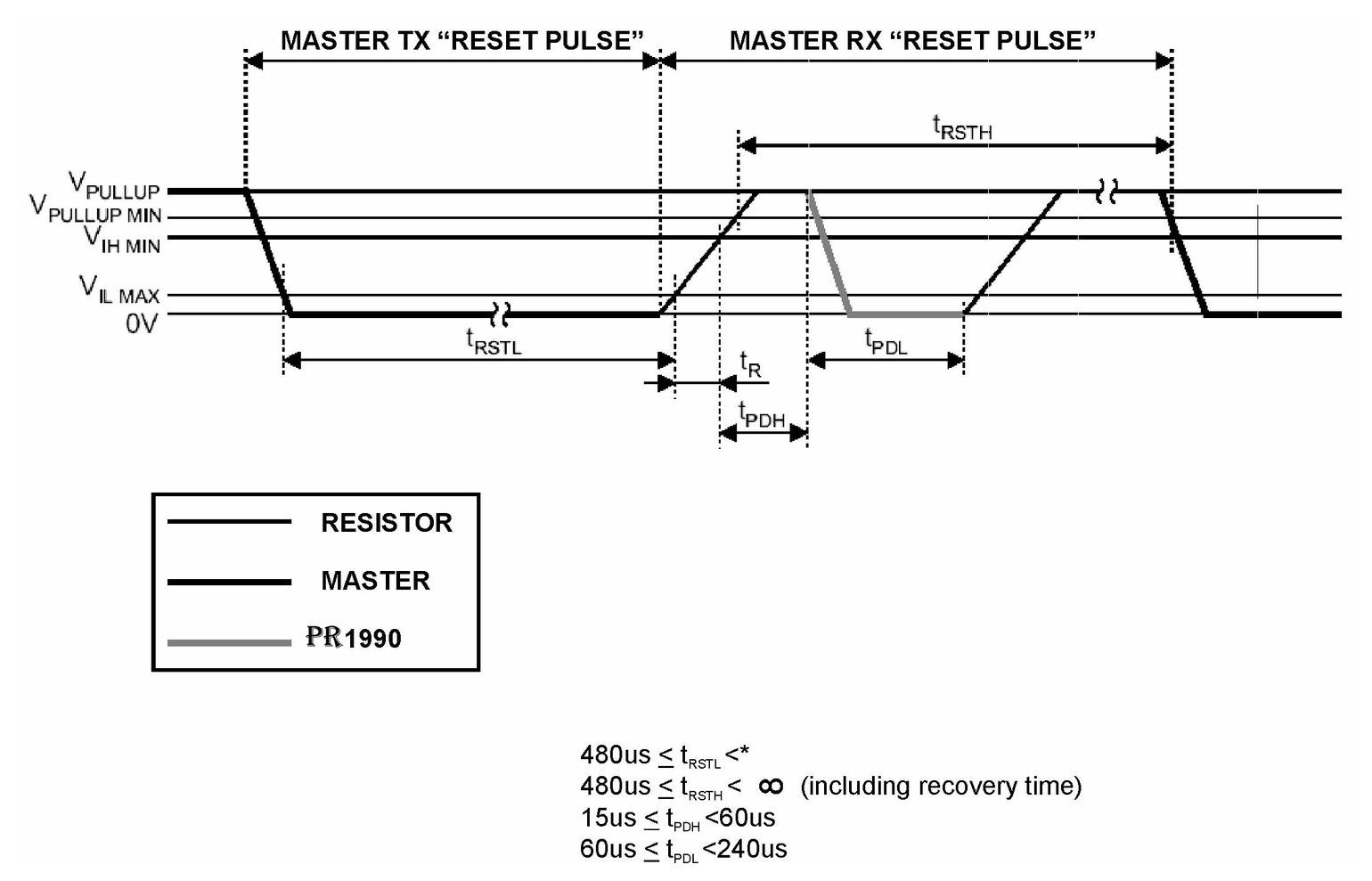
Every transaction starts here. The master pulls the line low for at least 480 µs, releases it, and the key answers with a presence pulse — that pulse is how the reader knows a key is touching the contact at all.
| Symbol | Device type | Min | Max |
|---|---|---|---|
t_RSTL | Reset pulse — master holds the line low | 480 µs | — |
t_RSTH | Reset high, including recovery time | 480 µs | ∞ |
t_PDH | Device stand-by before it answers | 15 µs | 60 µs |
t_PDL | Presence pulse — device pulls the line low | 60 µs | 240 µs |
One constraint that is easy to miss: t_RSTL plus the line rise time must stay under 960 µs, otherwise the reset masks interrupt signals from other devices sharing the bus.
2 · Write time slots
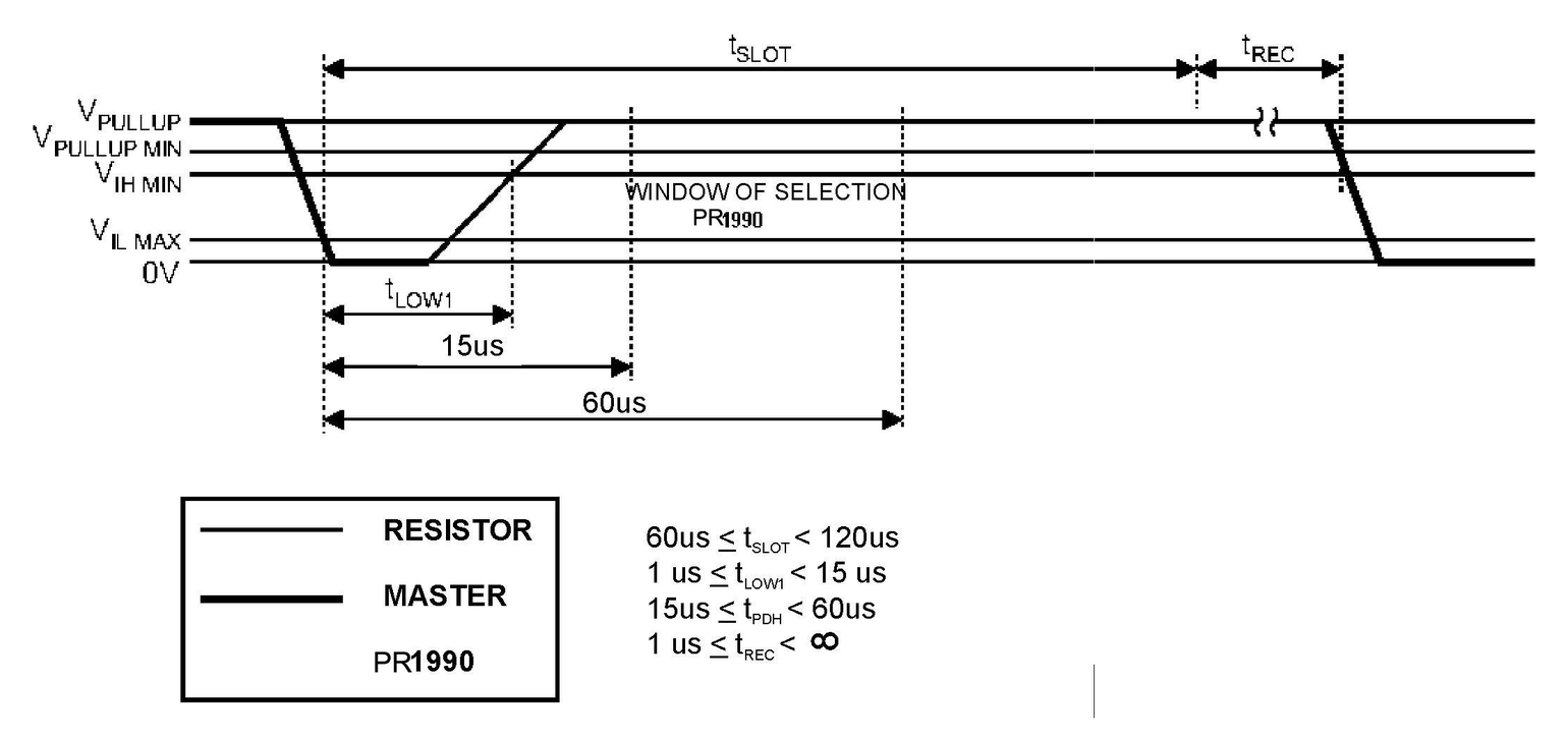
Both a 1 and a 0 begin with the master pulling the line low; only the duration differs. A short low (1–15 µs) means 1, a long low (60–120 µs) means 0. The key samples inside the selection window.
3 · Read time slots
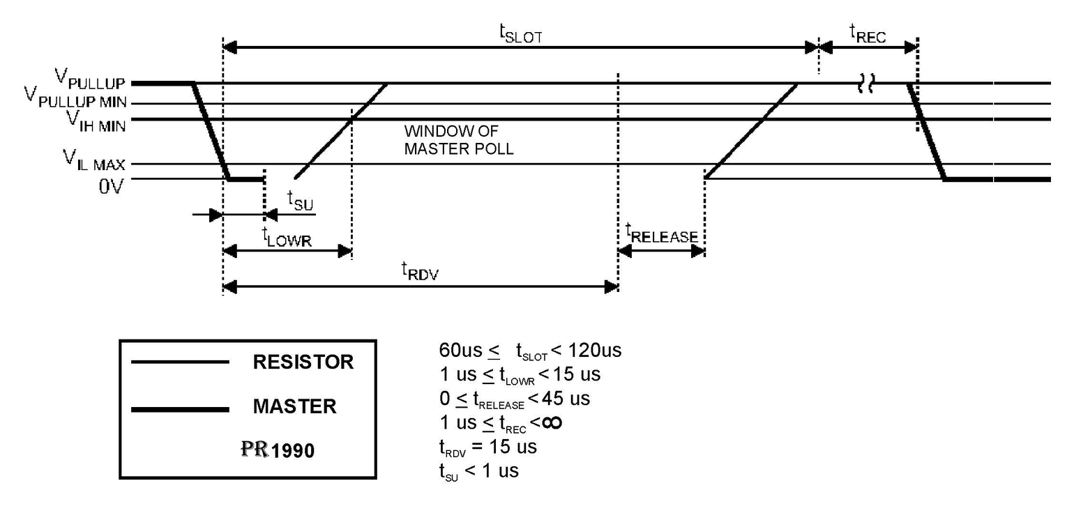
To read, the master pulses the line low briefly then releases it and samples. The catch is t_RDV: the data is only guaranteed valid for 15 µs from the falling edge, so a master that samples late reads garbage.
| Symbol | Device type | Min | Max |
|---|---|---|---|
t_SLOT | Duration of one read or write time slot | 60 µs | 120 µs |
t_LOW1 | Low period when writing a 1 | 1 µs | 15 µs |
t_LOW0 | Low period when writing a 0 | 60 µs | 120 µs |
t_RDV | Valid data window — master must sample by here | — | 15 µs |
t_RELEASE | Time for the device to vacate the bus | 0 | 45 µs |
t_SU | Data set-up time before read | — | 1 µs |
t_REC | Recovery between slots | 1 µs | ∞ |
ROM command codes
| Family code | Command | Notes |
|---|---|---|
33h / 0Fh | Read ROM | Returns the 8-bit family code, 48-bit serial and 8-bit CRC. Only valid with a single device on the bus. PR1990 answers to both 33h and 0Fh; a DS1990 answers only to 0Fh. |
55h | Match ROM | Not used on a 64-bit-ROM-only key — the device does not respond. |
CCh | Skip ROM | Not used on a 64-bit-ROM-only key — the device does not respond. |
F0h | Search ROM | Lets the master discover every ROM code on the bus by repeated bit / complement-bit / select steps. This is how multi-key buses are enumerated. |
Electrical limits
| Parameter | Symbol | Value |
|---|---|---|
| Pull-up supply range | V_PUP | 2.8 – 6.0 V |
| Logic “1” input voltage | V_IH | ≥ 2.2 V |
| Logic “0” input voltage | V_IL | −0.3 … +0.8 V |
| Low-level output voltage at 4 mA | V_OL | ≤ 0.4 V |
| Voltage at pins relative to GND | — | −0.5 … +7.0 V |
| Operating temperature | T_oper | −40 … +85 °C |
| Storage temperature | T_stg | −55 … +125 °C |
This table is provided as a working reference. For design-critical decisions always confirm against the current manufacturer datasheet.
Dallas, Maxim and iButton are trademarks of their respective owners. We manufacture compatible products and are not affiliated with them.