How to wire a Touch Memory reader (TM+, TM−, LED)
The four wires on a TM reader, what each one does, why the LED circuit is independent of the key circuit, and the mistakes that cause a reader to “not work” when it is actually wired backwards.
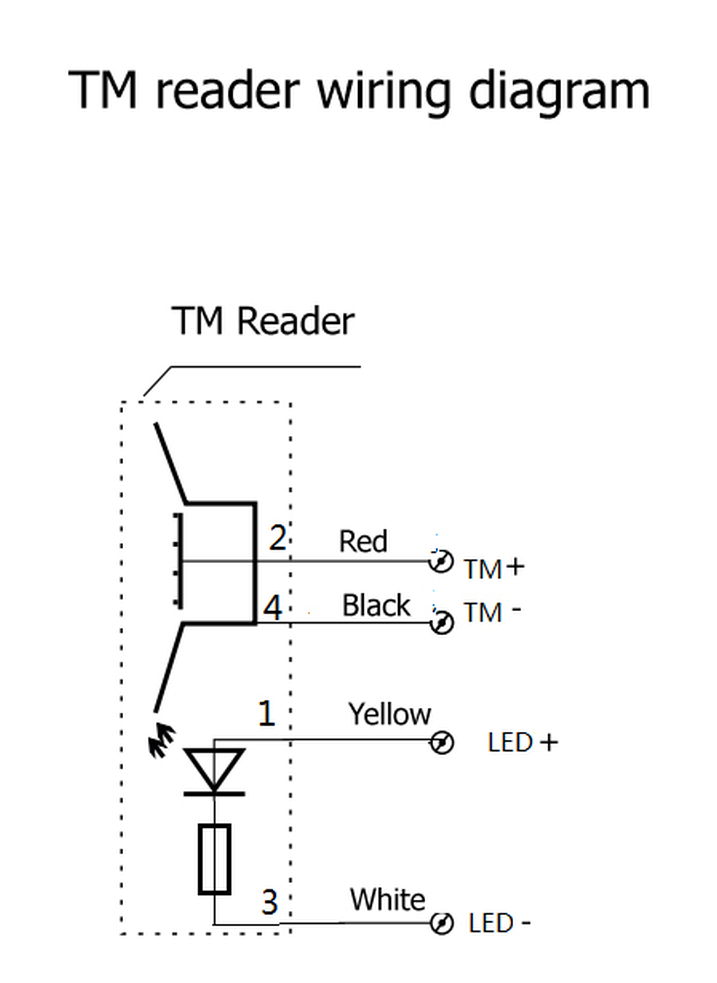
| Pin | Type | Protocol | Typical use |
|---|---|---|---|
2 | Red | TM + | Data line — the centre contact of the receptor. Goes to the controller’s TM/iButton data input. |
4 | Black | TM − | Ground return — the stainless shell of the receptor. Must share ground with the controller. |
1 | Yellow | LED + | Indicator anode, through a series current-limiting resistor. Driven by the controller, not by the key. |
3 | White | LED − | Indicator cathode. Keep the LED pair separate from the TM pair — they are not the same circuit. |
-
The LED is not powered by the key
This is the single most common misunderstanding. The key only closes the TM+/TM− circuit; the indicator is a separate LED pair that the controller switches to acknowledge a valid read. If you wire only TM+ and TM−, the reader still works — you just lose the visual feedback.
-
Reversing TM+ and TM− looks like a dead reader
The shell and the centre contact are not interchangeable. Swap them and the controller sees nothing at all, which is usually misdiagnosed as a faulty reader or faulty keys. Before replacing anything, check continuity: black must reach the metal body, red must reach the insulated centre pin.
-
Respect 1-Wire cable limits
The 1-Wire bus is forgiving but not unlimited. Keep the run short and use a twisted pair with the ground; long, unshielded, star-wired runs are where intermittent reads start. If a site needs long cable, use readers with a series resistor (the DS1990R-style approach) or move the controller closer.
-
Ground must be common
TM− is a ground return, not an isolated signal. If the reader and the controller sit on different power supplies without a shared ground, reads become erratic in a way that looks random. Bond the grounds first — it resolves a surprising share of “sometimes it works” complaints.
Mounting the reader
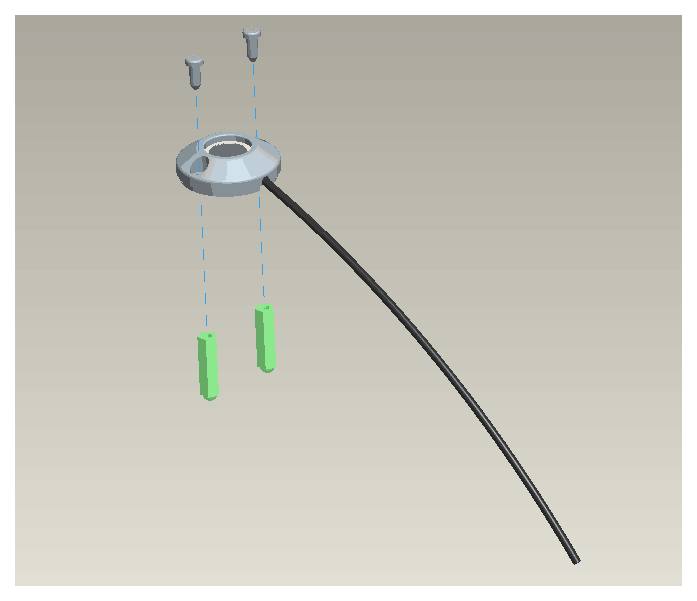
The flanged body drops into a round cut-out and is held by two screws into wall plugs. Route the tail before you seat the reader — once the flange is screwed down, there is no slack left to work with, and installers who leave it until last end up pulling the cable through a hole they can no longer reach.
Dallas, Maxim and iButton are trademarks of their respective owners. We manufacture compatible products and are not affiliated with them.